Head Tracking w FlySky GT3B and Telemetry Dashboard for Gmade GOM 1/10 Rock Crawler
The project is divided into 3 parts:
- Add head tracking (Channel 4-6) using Teensy 3.2 and toggle switching (Channel 7 & 8) functions in Flysky GT3B pistol transmitter
- Add front and back FPV camera into GOM
- Add telemetry dashboard function using ST7735 and Arduino Nano

(Thank you for sharing by Dylan Fairbanks for instruction of adding head tracking function and additional channels using Teensy 3.2 and Flysky GT3B)
- Basic programming skill
- Basic soldering skill
- Understanding of PPM and PWM
Components
- FlySky GT3B Transmitter and FS-R9B 8ch Receiver


- Teensy 3.2

- SkyZone 03O FPV Goggles (with Head Tracking Function)

- JR (Head Tracking) Cable(come with 03O FPV Goggles)

- 3.5mm Stereo Socket

- 2-ways Toggle Switch (3 Pins)
- 3-ways Toggle Switch (3 Pins)

- Axis Pan&Tilt Camera Mount


- 2 x Micro Servo


Steps
- First use of the Teensy 3.2 https://www.pjrc.com/teensy/first_use.html
- Please read through “Basic Teensyduino Usage” if this is your first time to use Teensy https://www.pjrc.com/teensy/td_usage.html
- Please cut USB Power at back of Teensy 3.2. https://www.pjrc.com/teensy/external_power.html
- Unscrew and open the top cover of GT3B
- Solder the wire (I am not a professional at soldering)
- Need cut original PPM Trace at the back of GT3 board
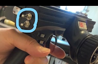
- Make the holes and install the 2 x toggle switch and 3.5MM audio socket


Programming
#include "PulsePosition.h"
#include <Servo.h>

Servo myservo;
PulsePositionInput RadioIn(FALLING);
PulsePositionInput TrackerIn(FALLING);
PulsePositionOutput MixOut(FALLING);

const uint8_t  RADIO_INPUT_PIN   = 22; //input the transmitter signal
const uint8_t  TRACKER_INPUT_PIN = 21; //input the head tracker signal
const uint8_t  MIX_OUT_PIN       = 20; //output the mixed signal

void setup() {
  Serial.begin(9600);
  RadioIn.begin(RADIO_INPUT_PIN);
  TrackerIn.begin(TRACKER_INPUT_PIN);
  MixOut.begin(MIX_OUT_PIN);
  myservo.attach(7);
  pinMode(5, INPUT_PULLUP); //for channel 8 two ways toggle switch - light switch
  pinMode(6, INPUT_PULLUP); //for channel 7 three was toggle swich - high-lo-dig gear
  pinMode(7, INPUT_PULLUP); //for channel 7 three was toggle swich - high-lo-dig gear
}

void loop() {
  int i, num;
  int j = 0;

//read channel 1-3 signal from transmitter FlySky GT3B
num = RadioIn.available();
if (num > 0) {
  for (i=1; i<=3; i++) {
   float val = RadioIn.read(i);
    MixOut.write(i, val);
  }
}

//read channel 5-7 signal from headtracker and map to 4,5,6. For setup of headtracking signal channel, please read the headtracker manual.
//For example, Skyzone 03O google: https://files.banggood.com/2016/12/SKY03%20Manual-V1.0(1).pdf
//Skyzone 03O google manual : The PPM channels can be set in the menu: CH5-CH6, CH5-CH7, CH5-CH8, CH6-CH7, CH6-CH8 and CH7-CH8.
num = TrackerIn.available();
if (num > 0) {
   for (i=1; i <= num; i++) {
    float val = TrackerIn.read(i);
    switch (i) {
       case 5:
          j = 4;
         break;
       case 6:
          j = 5;
          break;
        case 7:
         j = 6;
          break;
        case 8:
       j = 0;
        break;
      default:
    break;
   }
   if (j != 0) {
        MixOut.write(j, val);
   }
  }
 }


if (digitalRead(7)==LOW) {
   MixOut.write(7, 900);              // tell Ch7 servo to go to Dig position (servo turns to left)
  } else
   if (digitalRead(6)==LOW) {
   MixOut.write(7, 1950);             // tell Ch7 servo to go to High position (servo turns to right)
  } else
   MixOut.write(7, 1500);             // tell Ch7 servo to go to Low position (servo no turns)

 if (digitalRead(5)==LOW) {
   MixOut.write(8, 1950);             // tell Ch8 servo(LED light control) to be off
  } else
   MixOut.write(8, 1500);     	      // tell Ch8 servo(LED light control) to be on
}
Ch4-6 - Head Tracking testing
Ch7 - 3-ways Hi-Lo-Dig Gear(Servo) testing
Ch8 - 2-ways Toggle Switch Testing
PART 2: Add front and back FPV camera into GOM
Components
- Rush Tank FPV Transmitter
- 2 x FPV camera
- FPV camera channel switch
Connection Diagram

Remark:
Make sure that the input voltage of CAM and FPV transmitter can be supported by battery voltage
PART 3: Add telemetry dashboard function using ST7735 and Arduino Nano
The Telemetry Dashboard
Please refer to "Display a customized image in ST7735" for display customized image" in this blog
Pre-requisites:
- Basic of ST7735 and Arduino Nano
- https://www.electronics-lab.com/project/arduino-diy-photo-frame/
- https://learn.adafruit.com/1-8-tft-display?view=all
- Basic soldering skill
- Understanding of PPM and PWM
Components
Connection Diagram

Programming
#include <SPI.h>
#include <Adafruit_GFX.h>
#include <Adafruit_ST7735.h> // include Hardware library
#define TFT_CS 10
#define TFT_RST 9
#define TFT_DC 8
#define TFT_SCLK 13
#define TFT_MOSI 11
Adafruit_ST7735 tft = Adafruit_ST7735(TFT_CS, TFT_DC, TFT_RST);
#define BACKCOLOR 0x18E3
#define BARCOLOR 0x0620
#define SCALECOLOR 0xFFFF
#define BLACK 0x0000
#define BLUE 0xF800
#define PURPLE 0xF81F
#define CYAN 0xFFE0
#define WHITE 0xFFFF
#define GRAY 0x8410
#define RED 0xF800
#define ORANGE 0xFA60
#define YELLOW 0xFFE0
#define LIME 0x07FF
#define GREEN 0x07E0
#define AQUA 0x04FF
#define MAGENTA 0xF81F
#define PINK 0xF8FF
const int analogIn = A0;
int RawValue = 0;
int LastPercent = 0;
double throttle;
int gear;
int val=0;
int preval=0;
int FNB=0;
int preFNB=0;
int meter=0;
int premeter=0;
int gearval=0;
int pregearval=0;
// Bear Logo
const unsigned char bearlogo [] PROGMEM = {
0x00, 0x00, 0x00, 0x00, 0x00, 0x00, 0x00, 0x00, 0x00, 0x00, 0x00, 0x00, 0x00, 0x00, 0x00, 0x00,
0x00, 0x00, 0x00, 0x00, 0x01, 0xfc, 0x00, 0x00, 0x00, 0x00, 0x07, 0xff, 0x00, 0x00, 0x00, 0x00,
0x1f, 0x3f, 0x80, 0x00, 0x00, 0x00, 0x7c, 0x07, 0xc0, 0x00, 0x00, 0x03, 0xf0, 0x01, 0xf0, 0x00,
0x00, 0x0f, 0xe0, 0x31, 0xf8, 0x00, 0x00, 0x1f, 0xe1, 0xff, 0xfc, 0x00, 0x00, 0x7f, 0xff, 0x0f,
0xfe, 0x00, 0x00, 0xfe, 0x00, 0x01, 0xff, 0x00, 0x01, 0xfe, 0x00, 0x00, 0x3f, 0x80, 0x03, 0xf6,
0x00, 0x00, 0x1f, 0xc0, 0x07, 0xef, 0x00, 0x00, 0x1f, 0xe0, 0x0f, 0x9b, 0x00, 0x00, 0x1f, 0xe0,
0x0f, 0xb2, 0x00, 0x00, 0x3f, 0xe0, 0x0f, 0xe4, 0x00, 0x00, 0x3d, 0xf0, 0x1f, 0x64, 0x00, 0x00,
0x3d, 0xf0, 0x1f, 0x40, 0x00, 0x00, 0x1c, 0xf0, 0x1f, 0xc0, 0x00, 0xc0, 0x3e, 0xf0, 0x1f, 0x40,
0x00, 0xe0, 0x30, 0xf0, 0x1f, 0x60, 0x01, 0xe0, 0x61, 0xf8, 0x1f, 0x60, 0x01, 0xf0, 0xc1, 0xf8,
0x1f, 0x60, 0x00, 0x18, 0x01, 0xf0, 0x1d, 0xc0, 0x00, 0x18, 0x01, 0xf0, 0x1d, 0x80, 0x00, 0x10,
0x01, 0xf0, 0x1d, 0x80, 0x00, 0x00, 0x01, 0xf0, 0x0c, 0x00, 0x00, 0x00, 0x01, 0xf0, 0x0f, 0x10,
0x00, 0x00, 0x01, 0xf0, 0x1f, 0x20, 0x00, 0x00, 0x03, 0xe0, 0x1f, 0x60, 0x00, 0x00, 0x03, 0xe0,
0x1f, 0xe0, 0x00, 0x00, 0x03, 0xc0, 0x1f, 0xc0, 0x00, 0x00, 0x03, 0x80, 0x3f, 0xc0, 0x00, 0x00,
0x03, 0x80, 0x3f, 0xe0, 0x00, 0x00, 0x07, 0x00, 0x3f, 0xe0, 0x1f, 0x80, 0x06, 0x00, 0x1f, 0xf8,
0x1f, 0x00, 0x06, 0x00, 0x0f, 0xfc, 0x1e, 0x00, 0x0c, 0x00, 0x07, 0xfc, 0x06, 0x00, 0x0c, 0x00,
0x07, 0xf8, 0x02, 0x00, 0x08, 0x00, 0x3f, 0xf0, 0x00, 0x00, 0x18, 0x00, 0x0f, 0xf0, 0x00, 0x00,
0x10, 0x00, 0x0f, 0xf8, 0x02, 0x00, 0x30, 0x00, 0x0f, 0xf8, 0x00, 0x00, 0x30, 0x00, 0x07, 0xfc,
0x06, 0x00, 0x70, 0x00, 0x00, 0x7e, 0x0c, 0x00, 0x70, 0x00, 0x00, 0x7e, 0xf0, 0x01, 0xf0, 0x00,
0x00, 0x01, 0xff, 0xff, 0xf0, 0x00, 0x00, 0x00, 0x7f, 0xff, 0xc0, 0x00, 0x00, 0x00, 0x00, 0x00,
0x00, 0x00, 0x00, 0x00, 0x00, 0x00, 0x00, 0x00, 0x00, 0x00, 0x00, 0x00, 0x00, 0x00, 0x00, 0x00,
0x00, 0x00, 0x00, 0x00
};
// gomlogo, 47x18px
const unsigned char gomlogo [] PROGMEM = {
0x00, 0x00, 0x00, 0x00, 0x00, 0x00, 0x1f, 0xf0, 0x3f, 0xe1, 0xe0, 0x78, 0x3f, 0xf8, 0x7f, 0xf1,
0xf0, 0xf8, 0x7f, 0xfc, 0xff, 0xf9, 0xf0, 0xf8, 0x7c, 0x7c, 0xf8, 0xf9, 0xf9, 0xf8, 0x78, 0x00,
0xf0, 0x79, 0xff, 0xf8, 0x78, 0xfc, 0xf0, 0x79, 0xff, 0xf8, 0x78, 0x7c, 0xf0, 0x79, 0xff, 0xf8,
0x78, 0x7c, 0xf0, 0x79, 0xef, 0x78, 0x7f, 0xfc, 0xff, 0xf9, 0xe6, 0x78, 0x3f, 0xfc, 0x7f, 0xf1,
0xe0, 0x78, 0x1f, 0xec, 0x3f, 0xe1, 0xc0, 0x38, 0x00, 0x00, 0x00, 0x00, 0x00, 0x00, 0x29, 0xce,
0xa1, 0xd2, 0xe7, 0x48, 0x2f, 0x5a, 0xe3, 0xfa, 0xc4, 0x38, 0x3f, 0x58, 0xe3, 0xda, 0xf7, 0xb0,
0x2f, 0xde, 0xb3, 0xfe, 0xf7, 0xb0, 0x00, 0x00, 0x00, 0x00, 0x00, 0x00
};
void setup() {
Serial.begin(9600);
pinMode(6, INPUT); //get throttle signal from ch2
pinMode(4, INPUT); //get hi-lo-dig signal from ch7
tft.initR(INITR_BLACKTAB);
tft.fillScreen(BACKCOLOR); // back colour in background of ST7735
tft.setRotation(1); //set as landscape orientation
//display header in dashboard
tft.setTextColor(WHITE);
tft.setCursor(10,11);
tft.setTextSize(1);
tft.println("GOM TELEMETRY DASHBOARD");
//draw marker of acceleration bar
tft.drawLine(5,40,150,40,GRAY);
tft.setTextColor(WHITE);
tft.setCursor(5,45);
tft.println("1");
tft.setCursor(25,45);
tft.println("2");
tft.setCursor(45,45);
tft.println("3");
tft.setCursor(65,45);
tft.println("4");
tft.setCursor(85,45);
tft.println("5");
tft.setCursor(105,45);
tft.println("6");
tft.setCursor(125,45);
tft.println("7");
tft.setCursor(145,45);
tft.println("8");
//Print "0" as acceleration meter as default
tft.setTextColor(WHITE);
tft.setCursor(45,62);
tft.setTextSize(4);
tft.println("0");
//Print "N" as default
tft.setTextColor(WHITE);
tft.setCursor(15,66);
tft.setTextSize(3);
tft.println("N");
//display hi-lo-dig gear
tft.fillCircle(20,116,5,GRAY);
tft.fillCircle(50,116,5,GREEN);
tft.fillCircle(80,116,5,GRAY);
tft.drawLine(25,116,45,116,WHITE);
tft.drawLine(55,116,75,116,WHITE);
tft.setTextColor(WHITE);
tft.setCursor(16,103);
tft.setTextSize(1);
tft.println("HI");
tft.setTextColor(WHITE);
tft.setCursor(46,103);
tft.setTextSize(1);
tft.println("LO");
tft.setTextColor(WHITE);
tft.setCursor(73,103);
tft.setTextSize(1);
tft.println("DIG");
tft.drawBitmap(110, 55, bearlogo, 47, 54, WHITE); //draw bear logo
tft.drawBitmap(110, 107, gomlogo, 47, 18, WHITE); //draw gom logo
}
void loop(){
int newPercent;
int i;
int j=1;
int k=1;
int colour;
int diff;
int FNBdiff;
//get signal from pin6 (Ch2)
throttle = pulseIn(6, HIGH);
if (throttle>=1514) //car moving backward
FNB = -1;
else if (throttle<1479) //car moving forward
FNB = 1;
else //car in neutral
FNB = 0;
if (throttle<1479){ //if moving forward, val is for acceleration bar
val = map(throttle, 1479, 989,0,7);
meter = map(throttle, 1479, 989, 0, 99); //map the throttle signal to 0-99, meter is for acceleration meter
}
else {
val=0;
meter=0;
}
diff= val - preval; //calculate the different value for acceleration bar
if (diff>0) //acceleration, draw the colour bar
{
j=preval*20;
for (i=preval; i<=val ; i++){
if (i>=5)
else colour = RED;
if (i>=3)
else colour = YELLOW;
colour = GREEN;
Tft.fillRect(j+4, 27, 20, 10, colour);
j=j+20;
}
}
else if (diff <0) //deceleration, draw "black" bar
{
j=preval*20;
for (i=preval; i>=val ; i--){
tft.fillRect(j+4, 27, 20, 10, BLACK);
j=j-20;
}
}
preval=val;
//display "D" - Forward, "N" - Neutral, "R" - Backward
tft.setTextColor(PURPLE);
tft.setCursor(15,66);
tft.setTextSize(3);
if ((FNB-preFNB)!=0) {
if(FNB>0){
tft.setTextColor(GREEN);
tft.fillRect(15, 66, 20, 23, BLACK);
tft.println("D");
}
else
if (FNB<0){
tft.setTextColor(RED);
tft.fillRect(15, 66, 20, 23, BLACK);
tft.println("R");
}
else {
tft.setTextColor(WHITE);
tft.fillRect(15, 66, 20, 23, BLACK);
tft.println("N");
}
}
//display acceleration meter
if ((FNB-preFNB)!=0){ //display "0" if deceleration
tft.fillRect(45, 62, 60, 30, BLACK);
tft.setTextColor(WHITE);
tft.setCursor(45,62);
tft.setTextSize(4);
tft.println("0");
}
else
if (FNB>0){ //display "meter" if acceleration
if((meter-premeter)>1){
tft.fillRect(45, 62, 60, 30, BLACK);
tft.setTextColor(WHITE);
tft.setCursor(45,62);
tft.setTextSize(4);
tft.println(meter);
}
}
premeter=meter;
preFNB=FNB;
//display Hi-lo-Dig Gear
gear = pulseIn(4, HIGH);
if (gear<950){ //display Hi Gear
gearval=1;
if ((gearval-pregearval)!=0){
tft.fillCircle(20,116,5,GREEN);
tft.fillCircle(50,116,5,GRAY);
tft.fillCircle(80,116,5,GRAY);
}
}
else
if (gear>1900) { //display Dig Gear
gearval=-1;
if ((gearval-pregearval)!=0){
tft.fillCircle(20,116,5,GRAY);
tft.fillCircle(50,116,5,GRAY);
tft.fillCircle(80,116,5,GREEN);
}
}
else{
gearval=0;
if ((gearval-pregearval)!=0){ //display Lo Gear
tft.fillCircle(20,116,5,GRAY);
tft.fillCircle(50,116,5,GREEN);
tft.fillCircle(80,116,5,GRAY);
}
}
pregearval=gearval;
}
Dashboard - Throttle testing
Dashboard - Hi-Lo-Dig Gear testing

Comments
Post a Comment